- Markets
- Catalog
- Services & Solutions
- Newsroom
- Documents
- About Nexans
-
Nexans Insights
- Nexans Insights
-
Blog Posts
- Overview
- The path to effective fire safety in buildings
- Big data & AI
- Electrical and Fire Safety
- IoT
- Unveiling innovations transforming the industry
- Transforming buildings industry with 3D printing and modular construction
- Powering the digital change
- Unleashing the power of DC buildings
- Sustainable buildings for a brighter future
- Industry 1, 2, 3, 4... and 5.0
- Nexans copper odyssey
- Localizador de tiendas
- Search
- Contact us
- Compare
- Sign in

FREETOX 3x4/0 AWG 5kV 133%IL
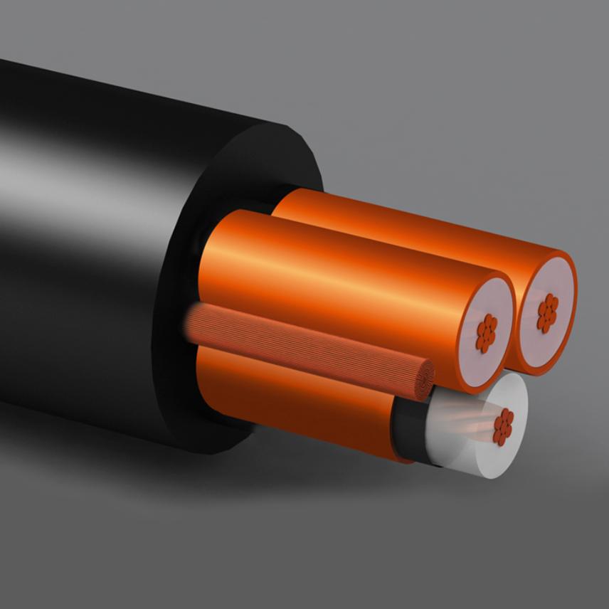
FREETOX 3x4/0 AWG 5kV 133%IL
Low fire hazard power cable for fixed installations in medium voltage systems.
Multi-core cable XLPE/LFH(Low Fire Hazard). 90°C. 5-8-15-25-35-46 kV according to ICEA S-93-639. 3,6/6 - 6/10 - 8,7/15 - 12/20 - 18/30 kV according to IEC 60502-2. Read moreDescription
Description
Standards
-
ProductASTM B 3; ASTM B 496; ASTM B 8; ICEA S-93-639; IEC 60228; IEC 60502-2
-
TestIEC 60332-1-2; IEC 60332-3-24 Cat.C; IEC 60684-2; IEC 60754-1; IEC 60754-2; IEC 61034-2
-
InternationalNES 713
Applications
Power shielded cable for fixed installations, used for connection of transformers, switchgears, GIS substations, motors, generators, feeders in distribution networks. Suitable to be installed directly buried, buried in ducts, in conduits, cable trays or in free air.
Construction: Multi-core cable.
Conductor: Compact-round stranded copper conductor. For AWG and kcmil sizes: class B according to ASTM B3, ASTM B8 and ASTM B496 according to requirements of ICEA S-93-639. For standard mm² sizes: class 2 according to IEC 60228.
Conductor shield: Extruded semiconducting material.
Insulation: Tree-Retardant crosslinked polyethylene (TR-XLPE) or crosslinked polyethylene (XLPE) with excellent electrical properties, good resistance to ozone and chemical agents.
Insulation shield: Extruded semiconducting material.
Metallic shield: Copper tape applied helically in intimate contact with the underlaying semiconducting layer, 12% nominal overlap.
Ground conductor (Optional): One or three flexible bare copper conductors, class 5 according to IEC 60228, in contact with the metallic shields.
Oversheath: Low fire hazard polyolefin (LFH), flame and fire retardant, low smoke emission, resistant to weather and UV radiation. Color upon request.
Marking: NEXANS CHILE FREETOX "size" "Rated voltage" Cu XLPE "Nominal Insulation Thickness" (1) 90°C "Manuf. order" "Date"
(1) Nominal Insulation Thickness information on marking only applies for cables according to ICEA S-93-639.
Design Alternatives
FREETOX-RAT: Resistant to rodent attack.
FREETOX-MAG: Armored cable with galvanized steel wires.
FREETOX-MZG: Armored cable with two flat galvanized steel tapes.
FREETOX-MAZG: Armored cable with galvanized steel wires and two flat galvanized steel tapes.
INSTALLATION CONDITIONS FOR CURRENT CARRYING CAPACITIES_MV MULTI-CORE CABLES
(1) Current carrying capacities based on NEC/NFPA 70 for installations were ducts and cables are not directly exposed to solar radiation.
De-rating factors must be applied according to specific instalation conditions.
INSTALLATION CONDITIONS FOR CURRENT CARRYING CAPACITIES_MV MULTI-CORE CABLES

Characteristics
Characteristics
Construction characteristics
Construction characteristics
Dimensional characteristics
Dimensional characteristics
Electrical characteristics
Electrical characteristics
Mechanical characteristics
Mechanical characteristics
Usage characteristics
Usage characteristics
Resources
Resources
Documentation
Our websites
Select your country to find our products and solutions
-
Africa
- Africa
- Ghana
- Ivory Coast
- Morocco
- North West Africa
- Americas
- Asia
- Europe
- Oceania